The Internet of Things (IoT) allows objects to be identified and controlled from a distance using existing network infrastructure, opening up new possibilities. greater efficiency, accuracy, and financial benefit through more direct contact between the actual and virtual worlds and computer-based systems.In order to maximise water consumption and maintain a green environment, it is important to irrigate more effectively as water supplies become increasingly scarce and polluted. The goal of this project is to create a smart houseplant watering and monitoring system that analyses and records environmental factors to help plants thrive. The sensors collect and evaluate data regarding changing weather and soil moisture levels before sending timely warnings to the user’s Android phone.
Material Required for making Plant Monitoring and control system:-
NodeMCU is an Internet of Things (IoT)-focused open-source Lua-based firmware and development board[9]. It includes software for Espressif Systems’ ESP8266 Wi-Fi SoC as well as hardware for the ESP-12 module.The major argument for choosing this is that it is cheap and includes a built-in Wi-Fi module[10]. Because it is similar to Arduino, it can be programmed using the Arduino IDE software. It has ten General Purpose Input/Output pins for connecting to external devices. A standard NodeMCU, complete with pin numbers.
Soil Moisture Sensor
The Soil Moisture Sensor is a straightforward breakout for determining the moisture content of soil and other similar materials. The soil moisture sensor is simple to set up and operate. The sensor’s two big exposed pads serve as probes, and combined they operate as a variable resistor.The greater the amount of water in the soil, the better the conductivity between the pads will be, resulting in a lower resistance and a larger SIGout[13]. It’s commonly used in greenhouses to regulate water supply and other bottle enhancements. Experiments in biology to track the amount of water in the soil.
Specifications: Working voltage: 5V Working current: <20 mA Interface: Analog Working Temperature: 10°C~30°C
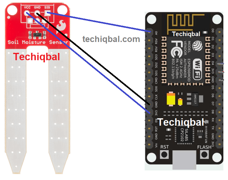
Step 1:- Circuit of NodeMcu and soil moisture sensor of Plant Monetoring and control system
DHT 11
The dht11 sensor, which combines a temperature and humidity sensor, typically outputs either digital or analog data. It contains information about the temperature around the plant if it needs extra sunshine and the degree of humidity in the surrounding environment. Water vapor is detected by measuring the electrical resistance between the two electrodes. The humidity sensing component consists of the electrode and the substrate, which is responsible for retaining moisture while in contact with the surface. Ions are released by the substrate. The conductivity between the electrodes rises as soon as water vapour is absorbed by it. The calibration result of the dht11 sensor is quite accurate. Because of its small size and low power consumption, the DHT11 sensor has a wide range of uses. It can also transmit signals over a distance of up to 20 meters. The product we used was a four-pin single row pin box.
Specification: Temperature range: 0 to 50° C error of + 2° C. Humidity: 20-90% RH + 5% RH Interface: digital
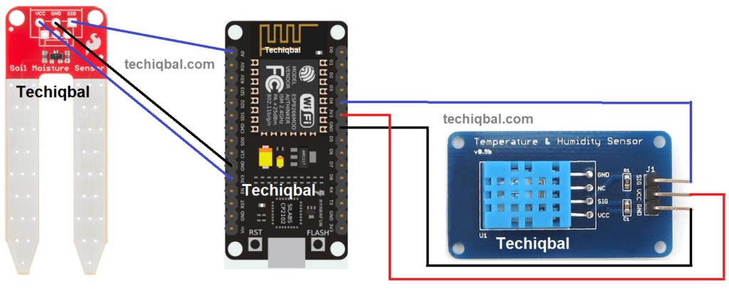
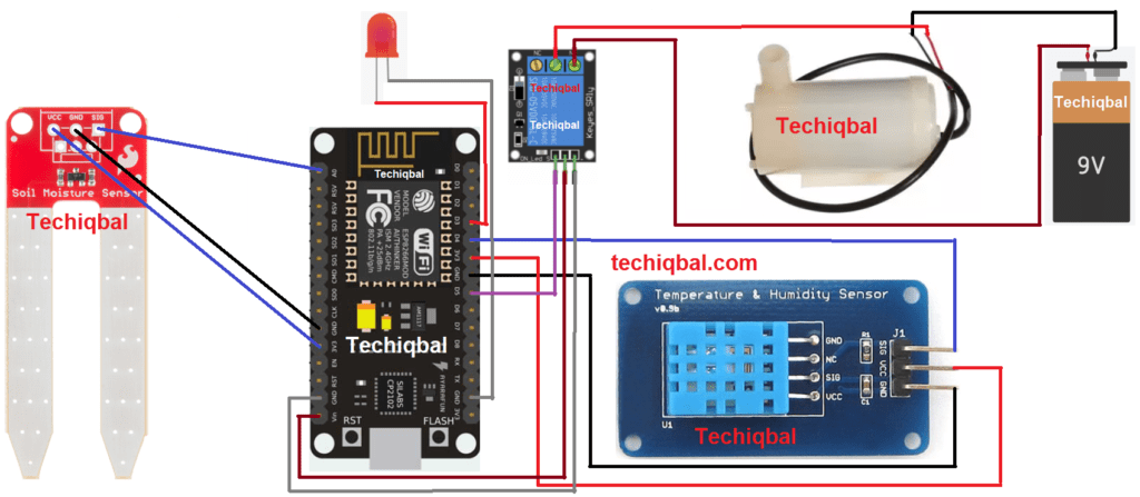
Step 2:- Circuit of NodeMcu, Humidity Temperature and soil moisture sensor for Plant Monitoring and control system
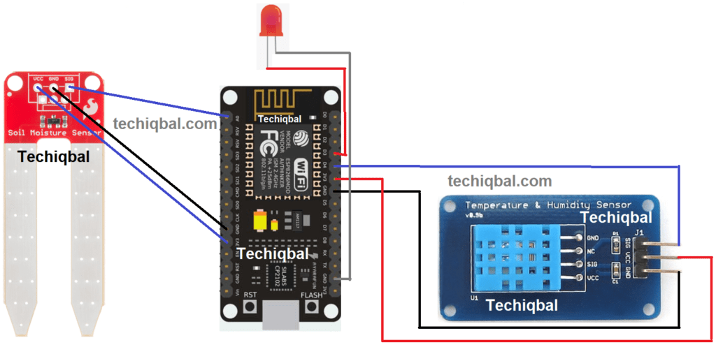
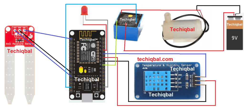
Step 3:- Circuit of NodeMcu, Humidity Temperature, LED and soil moisture sensor for Plant Monitoring and control system
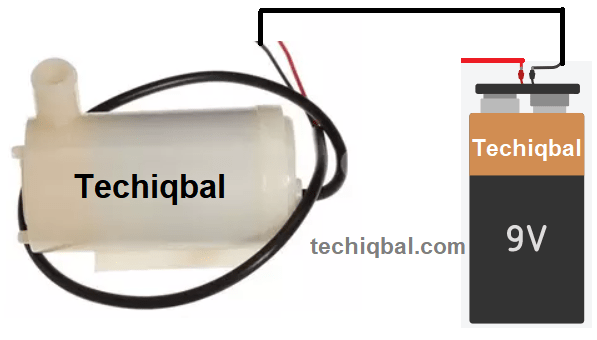
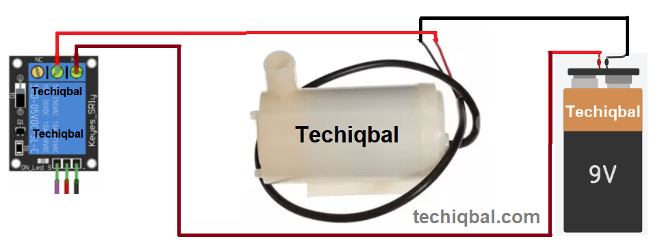
Step 4:- Circuit of water pump and battery for Plant Monitoring and control system
Relay
Within a relay, there is a core with copperwire wrapped around it (the coil). Under normal conditions, the switch (armature) remains in contact with the normally closed (NC) terminal. An electromagnetic field is generated when power is applied to the coil, and the coil begins to function as a magnet, attracting the armature to the normally open terminal (NO). At their most fundamental level, relays are nothing more than that. Aside from that, there are a variety of other types of relays, such as solid state and thermal relays, all of which have distinct functioning processes but serve the same purpose. This portion is used to regulate the small dc pump, which is used to water the plants automatically, and the flow is regulated by a relay. Relays are used to switch control circuits that handle lower currents. Furthermore, it can manage even greater voltages and amperes with the assistance of amplification.
Step 5:- Circuit of water pump, Relay and battery for Plant Monitoring and control system
Step 6:- Plant Monitoring system circuit diagram with relay Module
Step 6:- Plant Monitoring system circuit diagram with relay
Blynk APP
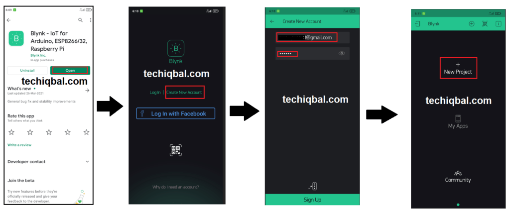
Blynk is a platform that allows you to control Arduino, Raspberry Pi, and other devices via the Internet using IOS and Android applications. It’s a digital dashboard where you may drag and drop widgets to create a graphic interface for your project. Blynk is a programme that allows you to create your own apps. It can be applied to a single project or a number of them. Virtual LEDs, buttons, value displays, and even a text terminal, as well as the ability to interact with one or more devices, may be incorporated in any project.
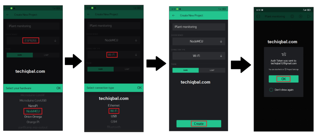
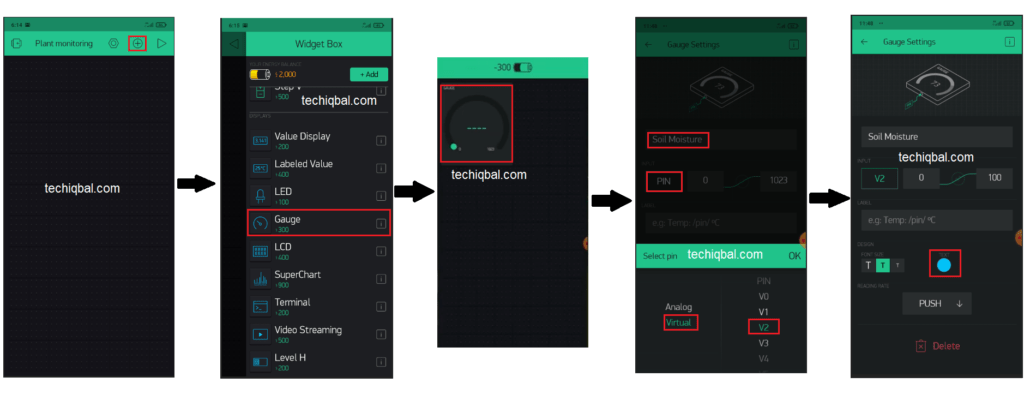
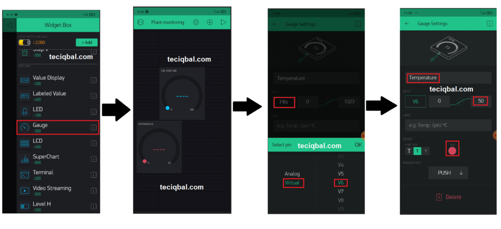
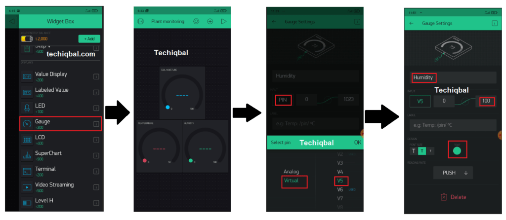
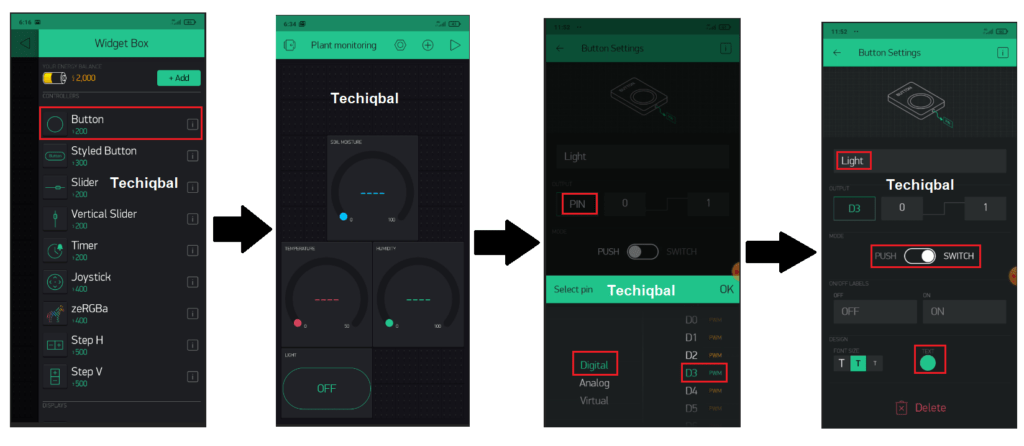
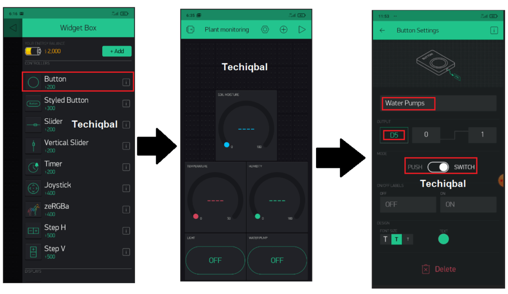
Step 7:- Blynk app setup for Plant Monitoring and control system
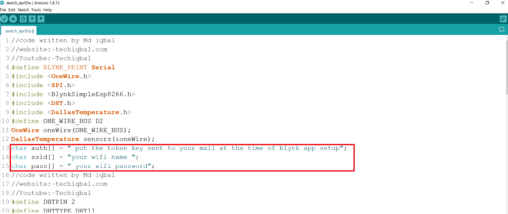
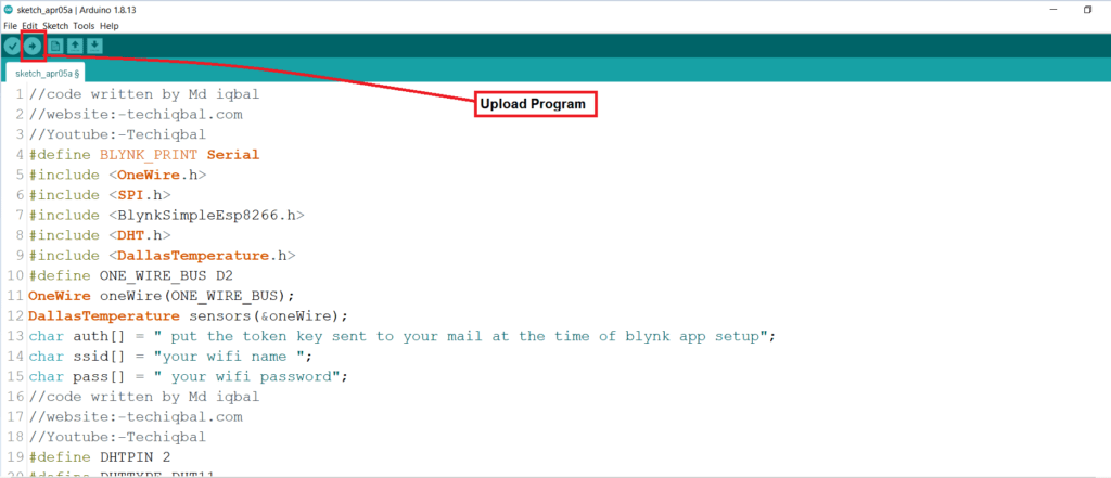
Step 8 :- Code for Plant Monitoring and control system
Note :- if you face compiling error then remove all the " double inverted coma in the code and type manually from the keyboard
//code is written by Md iqbal //website:-techiqbal.com //Youtube:-Techiqbal #define BLYNK_PRINT Serial #include <OneWire.h> #include <SPI.h> #include <BlynkSimpleEsp8266.h> #include <DHT.h> #include <DallasTemperature.h> #define ONE_WIRE_BUS D2 OneWire oneWire(ONE_WIRE_BUS); DallasTemperature sensors(&oneWire); char auth[] =”BOsoqmyvsdJSenk51n6EplHN0jqela_aajwi”; char ssid[] = “Iqbal”; char pass[] = “Password”; //code written by Md iqbal //website:-techiqbal.com //Youtube:-Techiqbal #define DHTPIN 2 #define DHTTYPE DHT11 DHT dht(DHTPIN, DHTTYPE); SimpleTimer timer; void sendSensor() { float h = dht.readHumidity(); float t = dht.readTemperature();
if (isnan(h) || isnan(t)) { Serial.println(“Failed to read from DHT sensor!”); return; }
Blynk.virtualWrite(V5, h); //V5 is for Humidity Blynk.virtualWrite(V6, t); //V6 is for Temperature } void setup() { Serial.begin(9600); dht.begin();
timer.setInterval(1000L, sendSensor); Blynk.begin(auth, ssid, pass); sensors.begin(); } int sensor=0; int output=0; void sendTemps() { sensor=analogRead(A0); output=(145-map(sensor,0,1023,0,100)); //in place 145 there is 100(it change with the change in sensor) delay(1000); sensors.requestTemperatures(); float temp = sensors.getTempCByIndex(0); Serial.println(temp); Serial.print(“moisture = “); Serial.print(output); Serial.println(“%”); Blynk.virtualWrite(V1, temp); Blynk.virtualWrite(V2,output); delay(1000); } void loop() { Blynk.run(); timer.run(); sendTemps(); } //code written by Md iqbal //website:-techiqbal.com //Youtube:-Techiqbal
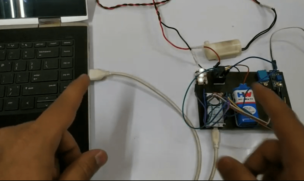
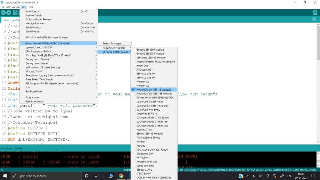
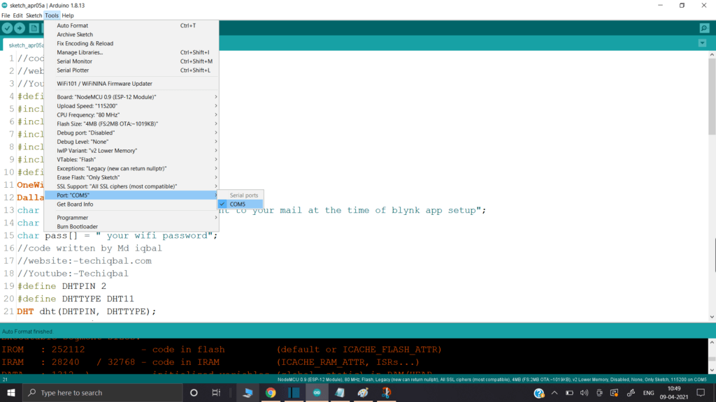
Connect node MCU to the Laptop
Change the following in the code according to your device
Upload the code of Plant Monitoring system in Node MCU
Get Best Experience From TechIqbal
"People who have no hold over their process of thinking are likely to be ruined by liberty of thought "